Damping
- The larger the damping ratio,
 , the larger the ratio of successive peak displacements in free vibration (
  ), and the quicker the decay of oscillations.
 - The damping ratio can be determined from measurements using the vibration theory of a single degree-of-freedom system.
- The damping ratio is a measure of the amount of damping in a structure which can effectively reduce structural vibration at resonance.
- The higher the amplitude of free vibration of a structure, the larger will be the critical damping ratio and the smaller will be the natural frequency.
Model Demonstrations
Observing the effect of damping in free vibrations
This set of models demonstrates the effect of damping provided by oil in free vibration, which can be observed by eyes.
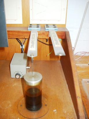
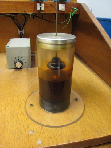
Fig. 17-2: Effect of the damping provided by oil.
Take a steel ruler and form a cantilever as shown in Fig. 15-9a. Give the tip of the ruler an initial displacement and release it. The steel ruler will perform many cycles of oscillation before it becomes stationary indicating that the damping ratio associated with steel alone is low.
Fig. 17-2a shows two identical steel strips acting as cantilevers. The only difference between the two cantilevers is that connected to the free end of the cantilever on the left is a vertical metal bar which in turn is attached to a disk immersed in oil. Fig. 17-2b shows the disk by lifting up the free end of the strip. Thus the effect of the oil and the device can be examined.
Press the free ends of the two cantilevers down by the same amount and then release them suddenly. It will be observed that the cantilever on the left only vibrates for a small number of cycles before stopping while the cantilever on the right oscillates through many cycles demonstrating the effect of viscous damping provided by the oil.
Hearing the effect of damping in free vibration
This set of models shows the effect of damping provided by rubber bands in free vibration, which can be heard by ears.
The sound heard from the free vibrations of a taut string, such as a violin string, links two different physical phenomena, sound transmission and the string vibrations, which both can be described using the same differential equation of motion. Thus hearing sound can be related to observing free vibrations, in this case those of a taut string.
Fig. 17-3 shows two identical steel bars, one is a bare bar and the other has rubber bands wrapped around it. The effect of the damping added by the rubber can be demonstrated as follows:
- Suspend the bare bar and give it a knock at its lower end using the other metal bar as shown in Fig. 17-3a. A sound will be generated from the bar for several seconds as it reverberates.
- Suspend the wrapped bar and give it a similar knock on the exposed metal part (Fig. 17-3b). This time only a brief dull sound is heard as the rubber wrapping dissipates much of the energy of the vibration.
Practical Examples
Damping ratio obtained from free vibration tests
The true damping characteristics of typical structural systems are normally very complex and difficult to define with few structures actually behaving as ideal single degree-of-freedom systems. Notwithstanding this, the earlier discussion of single degree-of-freedom systems can be useful when considering more complex practical structures.
A free vibration test was conducted on a full-sized eight-storey test building (Fig. 15-19) to identify the critical damping ratio of its fundamental mode [Ellis, B. R. and Ji, T., (1996)]. In order to amplify the displacements of the structure the building was shaken, by a set of vibrators mounted at the four corners on the roof of the building, at the fundamental frequency of the building. After the vibrators were suddenly stopped, the ensuing free vibrations of the roof of the building were measured. The decay of the vibrations in one of the two main directions of the building is shown in Fig. 15-18. As the excitation caused vibrations effectively only in the fundamental mode, the contributions of other modes of vibration to the decaying response of the structure were negligible.
Table 17-1: Natural frequency and damping ratio determined from various sections of decay
| Relative amplitude | Natural frequency (Hz) | Damping ratio (%) |
| 1.00 | 0.611 | 2.87 |
| 0.366 | 0.636 | 1.81 |
| 0.181 | 0.645 | 1.28 |
| 0.106 | 0.647 | 1.02 |
| 0.062 | 0.656 | 0.85 |
The natural frequency and damping ratio of the response of the structure can be determined from the records shown in Fig. 15-18. Five continuous 10s samples of vibrations were extracted from the response and a curve fitting technique was used to produce smooth curves from which the natural frequency and damping ratio could be determined. One such smoothed curve, superimposed on the measured curve, is shown in Fig. 17-4. The response frequency and damping ratio values extracted from the five samples are given in Table 17-1 and related to the amplitude of vibration at the start of each sample [Ellis, B. R. and Ji, T., (1996)].
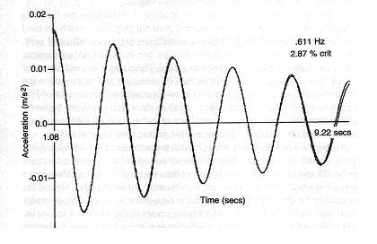
From Table 17-1 it can be observed that:
- the higher the amplitude of vibration, the smaller the natural frequency and the larger the damping ratio,
- the natural frequency for the relative amplitude of 1.00 is 6.86% lower than that for the relative amplitude of 0.062 while the damping ratio at the relative amplitude of 1.00 is 238% higher than that at the relative amplitude of 0.062.
When the building vibrated with small amplitudes, the relative movements between joints and other connections in the structure were small involving frictional forces doing less work leading to lower damping ratios than were found when amplitudes were larger with associated larger relative joint movements and friction related work. These variations have been observed in many different types of structure.
Damping ratio obtained from forced vibration tests
The forced vibration tests of the framed steel building for obtaining its resonance frequency are described in Section 16.4.3. The frequency spectrum obtained from the experiment and curve fitting are shown in Fig. 16-17.
The natural frequency and damping ratio obtained from the forced vibration tests were 0.617 Hz and 2.25% respectively. It can be noted that the measured values have a characteristic negative skew compared to the best-fit curve. This is typical of this type of measurement and shows one aspect of nonlinear behaviour as observed in free vibration tests of buildings and other structures.
It can be observed from Table 9-1 that the measurements from the forced vibration tests agree favourably with those obtained from the free vibration tests for relative amplitudes between 0.366 and 1.000. In general, forced vibration tests normally provide larger forces than free vibration tests. Therefore forced vibration tests frequently produce smaller values for natural frequencies and larger values for damping ratios than those obtained from free vibration tests.
Reducing footbridge vibrations induced by walking
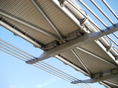
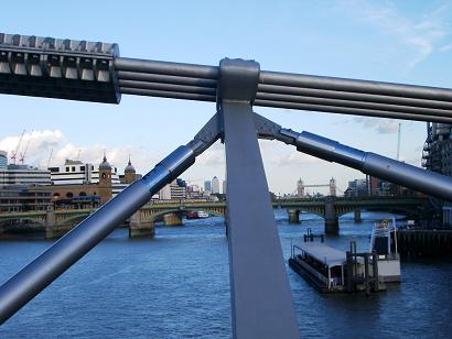
Damping devices installed on the London Millennium Footbridge
A total of 37 viscous dampers were installed on the London Millennium Footbridge in order to remove the lateral vibrations of the bridge which occured when people walked across the bridge. The majority of these dampers are situated beneath the bridge deck supported by transverse members (Fig. 17-5a). One end of each viscous damper is connected to the apex of a steel V brace, known as a chevron. The apex of the chevron is supported on roller bearings that provide vertical support but allow sliding in the other directions. The other ends of the chevron are fixed to the neighbouring transverse members [17.5]. Viscous dampers were also installed in the planes between the cables and the deck at the piers (Figure 17-5b) to provide damping of the lateral and lateral-torsional modes of vibration.
Reducing floor vibration induced by walking
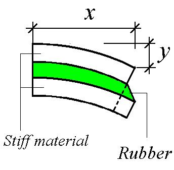
Damping can be introduced into concrete floors by sandwiching a layer of high damping material between the structural concrete floor and a protective concrete topping. This acts in a similar manner to the demonstration model described in Section 15.3.3.
During the bending of the floor induced by footfall vibrations, energy is dissipated through the shear deformation produced in the damping material by the relative deformations of the two concrete layers (Fig. 17-6). The technique was originally used to damp out vibrations of aircraft fuselage panels when the resonant frequencies of the panels were over 200 Hz.
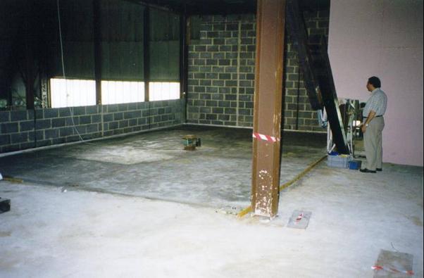
A floor panel, 6 m by 9 m , in the steel-frame test building at the BRE Cardington Laboratory was selected for testing with and without damping layers (Fig. 17-7). A variety of comparative tests were conducted included heel-drop tests, forced vibration tests and walking tests at different paces.
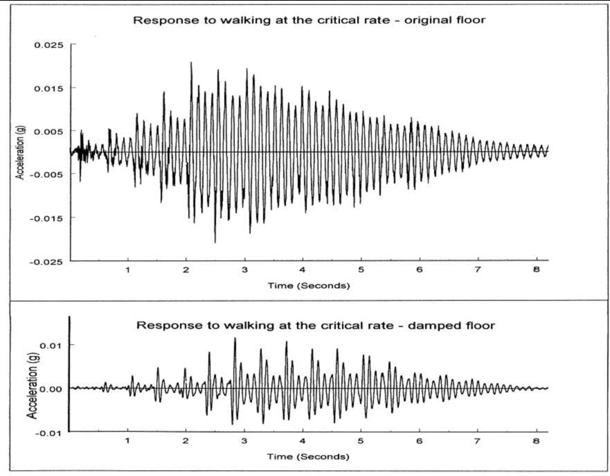
Fig. 17-8 shows the comparison of acceleration-time histories induced by the same individual walking on the floor panel without and with the damping layer. The benefit of the constrained damping layer in reducing the vibration of the floor is obvious.
References
17.1 Beards, C F, (1996), Structural Vibration: Analysis and Damping, Arnold, London, IBSN 0 340 64580 6.
17.2 Clough, R W and Penzien J, (1993), Dynamics of Structures, McGraw-Hill, New York, ISBN 0-07-11324-4.
17.3 Chopra A K, (1995), Dynamics of Structures, Prentice Hall Inc, New Jersey, ISBN 0-13-521063-1.
17.4 Ellis, B. R. and Ji, T., (1996), Dynamic testing and numerical modelling of the Cardington steel framed building from construction to completion, The Structural Engineer, Vol.74, No.11, pp.186-192.
17.5 Dallard, P, Fitzpatrick, A J, Flint,A, Le Bourva, S, Low, A, Ridsdill-Smith, R M and Willford, M, (2001) The London Millennium Footbridge, The Structural Engineer 79, pp.17-33.